LOAM的原理分析,源码解读,和运行调试
1.原理分析
2.源码解读
LOAM 的源码和中文详解
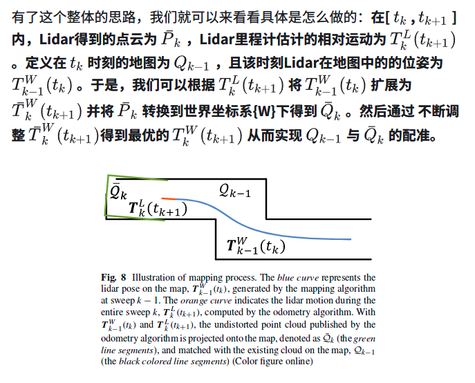
LOAM分为三个版本,对应不同的硬件设备,分别为:back_and_forth,continous以及velodyne,分别针对前后摆动的二维扫描仪、连续旋转的二维扫描仪及Velodyne16线程激光扫描仪。各版本都有相应的数据集,且目前较为流行的KITTI数据集也包含Velodyne16线程的激光数据,都可以用来对程序进行测试。本文以velodyne的版本为主,但实际上三种方法大同小异。LOAM的整体思想就是将复杂的SLAM问题分为:1. 高频的运动估计; 2. 低频(低一个数量级)的环境建图。整个系统的框架如图:
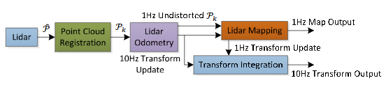
Lidar接收数据,首先进行Point Cloud Registretion 和 Lidar Odometry 以10Hz的频率进行运动估计和坐标转换,Lidar Mapping 以1Hz的频率构建三维地图。这样做主要是为了保证系统的实时性。下面再来看看代码的框架图:
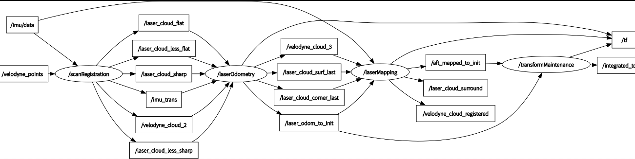
第一部分:scanRegistration.cpp
处理激光点云和IMU数据,提取论文中代表线和面的特征点,然后发布出去。看上图rqt_graph的图可以很直观了解。
首先对点云和IMU数据进行预处理,用于特征点的配准。根据点的曲率c来将点划分为不同的类别,到底是边特征还是面特征或则不是特征,公式如下:
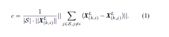
具体代码实现:
for (int i = 5; i < cloudSize - 5; i++) {//使用每个点的前后五个点计算曲率,因此前五个与最后五个点跳过float diffX = laserCloud->points[i - 5].x + laserCloud->points[i - 4].x + laserCloud->points[i - 3].x + laserCloud->points[i - 2].x + laserCloud->points[i - 1].x - 10 * laserCloud->points[i].x + laserCloud->points[i + 1].x + laserCloud->points[i + 2].x+ laserCloud->points[i + 3].x + laserCloud->points[i + 4].x+ laserCloud->points[i + 5].x;float diffY = laserCloud->points[i - 5].y + laserCloud->points[i - 4].y + laserCloud->points[i - 3].y + laserCloud->points[i - 2].y + laserCloud->points[i - 1].y - 10 * laserCloud->points[i].y + laserCloud->points[i + 1].y + laserCloud->points[i + 2].y+ laserCloud->points[i + 3].y + laserCloud->points[i + 4].y+ laserCloud->points[i + 5].y;float diffZ = laserCloud->points[i - 5].z + laserCloud->points[i - 4].z + laserCloud->points[i - 3].z + laserCloud->points[i - 2].z + laserCloud->points[i - 1].z - 10 * laserCloud->points[i].z + laserCloud->points[i + 1].z + laserCloud->points[i + 2].z+ laserCloud->points[i + 3].z + laserCloud->points[i + 4].z+ laserCloud->points[i + 5].z;//曲率计算cloudCurvature[i] = diffX * diffX + diffY * diffY + diffZ * diffZ;//记录曲率点的索引cloudSortInd[i] = i;//初始时,点全未筛选过cloudNeighborPicked[i] = 0;//初始化为less flat点cloudLabel[i] = 0;//每个scan,只有第一个符合的点会进来,因为每个scan的点都在一起存放if (int(laserCloud->points[i].intensity) != scanCount) {scanCount = int(laserCloud->points[i].intensity);//控制每个scan只进入第一个点//曲率只取同一个scan计算出来的,跨scan计算的曲率非法,排除,也即排除每个scan的前后五个点if (scanCount > 0 && scanCount < N_SCANS) {scanStartInd[scanCount] = i + 5;scanEndInd[scanCount - 1] = i - 5;}}}//第一个scan曲率点有效点序从第5个开始,最后一个激光线结束点序size-5scanStartInd[0] = 5;scanEndInd.back() = cloudSize - 5;
下面我们从main函数看起
int main(int argc, char** argv)
{ros::init(argc, argv, "scanRegistration");ros::NodeHandle nh;ros::Subscriber subLaserCloud = nh.subscribe<sensor_msgs::PointCloud2> ("/velodyne_points", 2, laserCloudHandler);ros::Subscriber subImu = nh.subscribe<sensor_msgs::Imu> ("/imu/data", 50, imuHandler);pubLaserCloud = nh.advertise<sensor_msgs::PointCloud2>("/velodyne_cloud_2", 2);pubCornerPointsSharp = nh.advertise<sensor_msgs::PointCloud2>("/laser_cloud_sharp", 2);pubCornerPointsLessSharp = nh.advertise<sensor_msgs::PointCloud2>("/laser_cloud_less_sharp", 2);pubSurfPointsFlat = nh.advertise<sensor_msgs::PointCloud2>("/laser_cloud_flat", 2);pubSurfPointsLessFlat = nh.advertise<sensor_msgs::PointCloud2>("/laser_cloud_less_flat", 2);pubImuTrans = nh.advertise<sensor_msgs::PointCloud2> ("/imu_trans", 5);ros::spin();return 0;
}
mian函数主要是订阅一些话题
现在讲一下这两个回调函数 laserCloudHandler()和imuHandler()
laserCloudHandler()该回调函数是这一节点的重点部分,主要功能是对接收到的点云进行预处理,完成分类。具体分类内容为:一是按照不同线,将点云保存在点云指针中;二是对其进行特征分类。
首先剔除异常点并计算起始和终止位置的角度:
//记录每个scan有曲率的点的开始和结束索引std::vector<int> scanStartInd(N_SCANS, 0);std::vector<int> scanEndInd(N_SCANS, 0);//当前点云时间double timeScanCur = laserCloudMsg->header.stamp.toSec();pcl::PointCloud<pcl::PointXYZ> laserCloudIn;//消息转换成pcl数据存放pcl::fromROSMsg(*laserCloudMsg, laserCloudIn);std::vector<int> indices;//移除空点pcl::removeNaNFromPointCloud(laserCloudIn, laserCloudIn, indices);//点云点的数量int cloudSize = laserCloudIn.points.size();//lidar scan开始点的旋转角,atan2范围[-pi,+pi],计算旋转角时取负号是因为velodyne是顺时针旋转float startOri = -atan2(laserCloudIn.points[0].y, laserCloudIn.points[0].x);//lidar scan结束点的旋转角,加2*pi使点云旋转周期为2*pifloat endOri = -atan2(laserCloudIn.points[cloudSize - 1].y,laserCloudIn.points[cloudSize - 1].x) + 2 * M_PI;然后遍历所有点,根据角度计算结果将其划分为不同的线:计算角度-->计算起始和终止位置-->插入IMU数据-->将点插入容器中
bool halfPassed = false;int count = cloudSize;PointType point;std::vector<pcl::PointCloud<PointType> > laserCloudScans(N_SCANS);for (int i = 0; i < cloudSize; i++) {//坐标轴交换,velodyne lidar的坐标系也转换到z轴向前,x轴向左的右手坐标系point.x = laserCloudIn.points[i].y;point.y = laserCloudIn.points[i].z;point.z = laserCloudIn.points[i].x;//计算点的仰角(根据lidar文档垂直角计算公式),根据仰角排列激光线号,velodyne每两个scan之间间隔2度float angle = atan(point.y / sqrt(point.x * point.x + point.z * point.z)) * 180 / M_PI;int scanID;//仰角四舍五入(加减0.5截断效果等于四舍五入)int roundedAngle = int(angle + (angle<0.0?-0.5:+0.5)); if (roundedAngle > 0){scanID = roundedAngle;}else {scanID = roundedAngle + (N_SCANS - 1);}//过滤点,只挑选[-15度,+15度]范围内的点,scanID属于[0,15]if (scanID > (N_SCANS - 1) || scanID < 0 ){count--;continue;}//该点的旋转角float ori = -atan2(point.x, point.z);if (!halfPassed) {//根据扫描线是否旋转过半选择与起始位置还是终止位置进行差值计算,从而进行补偿//确保-pi/2 < ori - startOri < 3*pi/2if (ori < startOri - M_PI / 2) {ori += 2 * M_PI;} else if (ori > startOri + M_PI * 3 / 2) {ori -= 2 * M_PI;}if (ori - startOri > M_PI) {halfPassed = true;}} else {ori += 2 * M_PI;//确保-3*pi/2 < ori - endOri < pi/2if (ori < endOri - M_PI * 3 / 2) {ori += 2 * M_PI;} else if (ori > endOri + M_PI / 2) {ori -= 2 * M_PI;} }//-0.5 < relTime < 1.5(点旋转的角度与整个周期旋转角度的比率, 即点云中点的相对时间)float relTime = (ori - startOri) / (endOri - startOri);//点强度=线号+点相对时间(即一个整数+一个小数,整数部分是线号,小数部分是该点的相对时间),匀速扫描:根据当前扫描的角度和扫描周期计算相对扫描起始位置的时间point.intensity = scanID + scanPeriod * relTime;//点时间=点云时间+周期时间if (imuPointerLast >= 0) {//如果收到IMU数据,使用IMU矫正点云畸变float pointTime = relTime * scanPeriod;//计算点的周期时间//寻找是否有点云的时间戳小于IMU的时间戳的IMU位置:imuPointerFrontwhile (imuPointerFront != imuPointerLast) {if (timeScanCur + pointTime < imuTime[imuPointerFront]) {break;}imuPointerFront = (imuPointerFront + 1) % imuQueLength;}if (timeScanCur + pointTime > imuTime[imuPointerFront]) {//没找到,此时imuPointerFront==imtPointerLast,只能以当前收到的最新的IMU的速度,位移,欧拉角作为当前点的速度,位移,欧拉角使用imuRollCur = imuRoll[imuPointerFront];imuPitchCur = imuPitch[imuPointerFront];imuYawCur = imuYaw[imuPointerFront];imuVeloXCur = imuVeloX[imuPointerFront];imuVeloYCur = imuVeloY[imuPointerFront];imuVeloZCur = imuVeloZ[imuPointerFront];imuShiftXCur = imuShiftX[imuPointerFront];imuShiftYCur = imuShiftY[imuPointerFront];imuShiftZCur = imuShiftZ[imuPointerFront];} else {//找到了点云时间戳小于IMU时间戳的IMU位置,则该点必处于imuPointerBack和imuPointerFront之间,据此线性插值,计算点云点的速度,位移和欧拉角int imuPointerBack = (imuPointerFront + imuQueLength - 1) % imuQueLength;//按时间距离计算权重分配比率,也即线性插值float ratioFront = (timeScanCur + pointTime - imuTime[imuPointerBack]) / (imuTime[imuPointerFront] - imuTime[imuPointerBack]);float ratioBack = (imuTime[imuPointerFront] - timeScanCur - pointTime) / (imuTime[imuPointerFront] - imuTime[imuPointerBack]);imuRollCur = imuRoll[imuPointerFront] * ratioFront + imuRoll[imuPointerBack] * ratioBack;imuPitchCur = imuPitch[imuPointerFront] * ratioFront + imuPitch[imuPointerBack] * ratioBack;if (imuYaw[imuPointerFront] - imuYaw[imuPointerBack] > M_PI) {imuYawCur = imuYaw[imuPointerFront] * ratioFront + (imuYaw[imuPointerBack] + 2 * M_PI) * ratioBack;} else if (imuYaw[imuPointerFront] - imuYaw[imuPointerBack] < -M_PI) {imuYawCur = imuYaw[imuPointerFront] * ratioFront + (imuYaw[imuPointerBack] - 2 * M_PI) * ratioBack;} else {imuYawCur = imuYaw[imuPointerFront] * ratioFront + imuYaw[imuPointerBack] * ratioBack;}//本质:imuVeloXCur = imuVeloX[imuPointerback] + (imuVelX[imuPointerFront]-imuVelX[imuPoniterBack])*ratioFrontimuVeloXCur = imuVeloX[imuPointerFront] * ratioFront + imuVeloX[imuPointerBack] * ratioBack;imuVeloYCur = imuVeloY[imuPointerFront] * ratioFront + imuVeloY[imuPointerBack] * ratioBack;imuVeloZCur = imuVeloZ[imuPointerFront] * ratioFront + imuVeloZ[imuPointerBack] * ratioBack;imuShiftXCur = imuShiftX[imuPointerFront] * ratioFront + imuShiftX[imuPointerBack] * ratioBack;imuShiftYCur = imuShiftY[imuPointerFront] * ratioFront + imuShiftY[imuPointerBack] * ratioBack;imuShiftZCur = imuShiftZ[imuPointerFront] * ratioFront + imuShiftZ[imuPointerBack] * ratioBack;}if (i == 0) {//如果是第一个点,记住点云起始位置的速度,位移,欧拉角imuRollStart = imuRollCur;imuPitchStart = imuPitchCur;imuYawStart = imuYawCur;imuVeloXStart = imuVeloXCur;imuVeloYStart = imuVeloYCur;imuVeloZStart = imuVeloZCur;imuShiftXStart = imuShiftXCur;imuShiftYStart = imuShiftYCur;imuShiftZStart = imuShiftZCur;} else {//计算之后每个点相对于第一个点的由于加减速非匀速运动产生的位移速度畸变,并对点云中的每个点位置信息重新补偿矫正ShiftToStartIMU(pointTime);VeloToStartIMU();TransformToStartIMU(&point);}}laserCloudScans[scanID].push_back(point);//将每个补偿矫正的点放入对应线号的容器}//获得有效范围内的点的数量cloudSize = count;最后更新总的点云laserCLoud
pcl::PointCloud<PointType>::Ptr laserCloud(new pcl::PointCloud<PointType>());for (int i = 0; i < N_SCANS; i++) {//将所有的点按照线号从小到大放入一个容器*laserCloud += laserCloudScans[i];}好了,截止到现在,我们已经把一帧杂乱的点云数据有条理的放在了容器里,下面就可以开始处理啦!
我们要在laserCloud中找特征点的候选点,该怎么找呢?最暴力的方法:遍历每个点(除了前五个和后五个),计算各点曲率并找到所有线的起点终点位置;这一步的代码就是开篇放的那个,就不在重复了。
参照论文对点位筛选的条件:1. 平面/直线与激光近似平行的点不能要; 2. 被遮挡的边缘点不能要
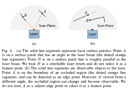
现在来看代码的实现:遍历所有点(除去前五个和后六个),判断该点及其周边点是否可以作为特征点位:当某点及其后点间的距离平方大于某阈值a(说明这两点有一定距离),且两向量夹角小于某阈值b时(夹角小就可能存在遮挡),将其一侧的临近6个点设为不可标记为特征点的点;若某点到其前后两点的距离均大于c倍的该点深度,则该点判定为不可标记特征点的点(入射角越小,点间距越大,即激光发射方向与投射到的平面越近似水平)。
for (int i = 5; i < cloudSize - 6; i++) {//与后一个点差值,所以减6float diffX = laserCloud->points[i + 1].x - laserCloud->points[i].x;float diffY = laserCloud->points[i + 1].y - laserCloud->points[i].y;float diffZ = laserCloud->points[i + 1].z - laserCloud->points[i].z;//计算有效曲率点与后一个点之间的距离平方和float diff = diffX * diffX + diffY * diffY + diffZ * diffZ;if (diff > 0.1) {//前提:两个点之间距离要大于0.1//点的深度float depth1 = sqrt(laserCloud->points[i].x * laserCloud->points[i].x + laserCloud->points[i].y * laserCloud->points[i].y +laserCloud->points[i].z * laserCloud->points[i].z);//后一个点的深度float depth2 = sqrt(laserCloud->points[i + 1].x * laserCloud->points[i + 1].x + laserCloud->points[i + 1].y * laserCloud->points[i + 1].y +laserCloud->points[i + 1].z * laserCloud->points[i + 1].z);//按照两点的深度的比例,将深度较大的点拉回后计算距离if (depth1 > depth2) {diffX = laserCloud->points[i + 1].x - laserCloud->points[i].x * depth2 / depth1;diffY = laserCloud->points[i + 1].y - laserCloud->points[i].y * depth2 / depth1;diffZ = laserCloud->points[i + 1].z - laserCloud->points[i].z * depth2 / depth1;//边长比也即是弧度值,若小于0.1,说明夹角比较小,斜面比较陡峭,点深度变化比较剧烈,点处在近似与激光束平行的斜面上if (sqrt(diffX * diffX + diffY * diffY + diffZ * diffZ) / depth2 < 0.1) {//排除容易被斜面挡住的点//该点及前面五个点(大致都在斜面上)全部置为筛选过cloudNeighborPicked[i - 5] = 1;cloudNeighborPicked[i - 4] = 1;cloudNeighborPicked[i - 3] = 1;cloudNeighborPicked[i - 2] = 1;cloudNeighborPicked[i - 1] = 1;cloudNeighborPicked[i] = 1;}} else {diffX = laserCloud->points[i + 1].x * depth1 / depth2 - laserCloud->points[i].x;diffY = laserCloud->points[i + 1].y * depth1 / depth2 - laserCloud->points[i].y;diffZ = laserCloud->points[i + 1].z * depth1 / depth2 - laserCloud->points[i].z;if (sqrt(diffX * diffX + diffY * diffY + diffZ * diffZ) / depth1 < 0.1) {cloudNeighborPicked[i + 1] = 1;cloudNeighborPicked[i + 2] = 1;cloudNeighborPicked[i + 3] = 1;cloudNeighborPicked[i + 4] = 1;cloudNeighborPicked[i + 5] = 1;cloudNeighborPicked[i + 6] = 1;}}}float diffX2 = laserCloud->points[i].x - laserCloud->points[i - 1].x;float diffY2 = laserCloud->points[i].y - laserCloud->points[i - 1].y;float diffZ2 = laserCloud->points[i].z - laserCloud->points[i - 1].z;//与前一个点的距离平方和float diff2 = diffX2 * diffX2 + diffY2 * diffY2 + diffZ2 * diffZ2;//点深度的平方和float dis = laserCloud->points[i].x * laserCloud->points[i].x+ laserCloud->points[i].y * laserCloud->points[i].y+ laserCloud->points[i].z * laserCloud->points[i].z;//与前后点的平方和都大于深度平方和的万分之二,这些点视为离群点,包括陡斜面上的点,强烈凸凹点和空旷区域中的某些点,置为筛选过,弃用if (diff > 0.0002 * dis && diff2 > 0.0002 * dis) {cloudNeighborPicked[i] = 1;}}
现在我们得到了一组有条理的点云,且把那些与我们想提取的特征不符的点标记了出来,那我们只需要从剩下的点中选择最好的那一波不就行了!为了保证特征点均匀的分布在环境中,将一次扫描划分为4个独立的子区域,每个子区域最多提供2个边缘点和4个平面点。我们只需要预先设定好阈值,就可以轻松加随意的将这些点分类了。代码中,把每个线分为6段进行处理,每段都将曲率按照升序排列。代码实现:
pcl::PointCloud<PointType> cornerPointsSharp;pcl::PointCloud<PointType> cornerPointsLessSharp;pcl::PointCloud<PointType> surfPointsFlat;pcl::PointCloud<PointType> surfPointsLessFlat;//将每条线上的点分入相应的类别:边沿点和平面点for (int i = 0; i < N_SCANS; i++) {pcl::PointCloud<PointType>::Ptr surfPointsLessFlatScan(new pcl::PointCloud<PointType>);//将每个scan的曲率点分成6等份处理,确保周围都有点被选作特征点for (int j = 0; j < 6; j++) {//六等份起点:sp = scanStartInd + (scanEndInd - scanStartInd)*j/6int sp = (scanStartInd[i] * (6 - j) + scanEndInd[i] * j) / 6;//六等份终点:ep = scanStartInd - 1 + (scanEndInd - scanStartInd)*(j+1)/6int ep = (scanStartInd[i] * (5 - j) + scanEndInd[i] * (j + 1)) / 6 - 1;//按曲率从小到大冒泡排序for (int k = sp + 1; k <= ep; k++) {for (int l = k; l >= sp + 1; l--) {//如果后面曲率点大于前面,则交换if (cloudCurvature[cloudSortInd[l]] < cloudCurvature[cloudSortInd[l - 1]]) {int temp = cloudSortInd[l - 1];cloudSortInd[l - 1] = cloudSortInd[l];cloudSortInd[l] = temp;}}}//挑选每个分段的曲率很大和比较大的点int largestPickedNum = 0;for (int k = ep; k >= sp; k--) {int ind = cloudSortInd[k]; //曲率最大点的点序//如果曲率大的点,曲率的确比较大,并且未被筛选过滤掉if (cloudNeighborPicked[ind] == 0 &&cloudCurvature[ind] > 0.1) {largestPickedNum++;if (largestPickedNum <= 2) {//挑选曲率最大的前2个点放入sharp点集合cloudLabel[ind] = 2;//2代表点曲率很大cornerPointsSharp.push_back(laserCloud->points[ind]);cornerPointsLessSharp.push_back(laserCloud->points[ind]);} else if (largestPickedNum <= 20) {//挑选曲率最大的前20个点放入less sharp点集合cloudLabel[ind] = 1;//1代表点曲率比较尖锐cornerPointsLessSharp.push_back(laserCloud->points[ind]);} else {break;}cloudNeighborPicked[ind] = 1;//筛选标志置位//将曲率比较大的点的前后各5个连续距离比较近的点筛选出去,防止特征点聚集,使得特征点在每个方向上尽量分布均匀for (int l = 1; l <= 5; l++) {float diffX = laserCloud->points[ind + l].x - laserCloud->points[ind + l - 1].x;float diffY = laserCloud->points[ind + l].y - laserCloud->points[ind + l - 1].y;float diffZ = laserCloud->points[ind + l].z - laserCloud->points[ind + l - 1].z;if (diffX * diffX + diffY * diffY + diffZ * diffZ > 0.05) {break;}cloudNeighborPicked[ind + l] = 1;}for (int l = -1; l >= -5; l--) {float diffX = laserCloud->points[ind + l].x - laserCloud->points[ind + l + 1].x;float diffY = laserCloud->points[ind + l].y - laserCloud->points[ind + l + 1].y;float diffZ = laserCloud->points[ind + l].z - laserCloud->points[ind + l + 1].z;if (diffX * diffX + diffY * diffY + diffZ * diffZ > 0.05) {break;}cloudNeighborPicked[ind + l] = 1;}}}//挑选每个分段的曲率很小比较小的点int smallestPickedNum = 0;for (int k = sp; k <= ep; k++) {int ind = cloudSortInd[k];//如果曲率的确比较小,并且未被筛选出if (cloudNeighborPicked[ind] == 0 &&cloudCurvature[ind] < 0.1) {cloudLabel[ind] = -1;//-1代表曲率很小的点surfPointsFlat.push_back(laserCloud->points[ind]);smallestPickedNum++;if (smallestPickedNum >= 4) {//只选最小的四个,剩下的Label==0,就都是曲率比较小的break;}cloudNeighborPicked[ind] = 1;for (int l = 1; l <= 5; l++) {//同样防止特征点聚集float diffX = laserCloud->points[ind + l].x - laserCloud->points[ind + l - 1].x;float diffY = laserCloud->points[ind + l].y - laserCloud->points[ind + l - 1].y;float diffZ = laserCloud->points[ind + l].z - laserCloud->points[ind + l - 1].z;if (diffX * diffX + diffY * diffY + diffZ * diffZ > 0.05) {break;}cloudNeighborPicked[ind + l] = 1;}for (int l = -1; l >= -5; l--) {float diffX = laserCloud->points[ind + l].x - laserCloud->points[ind + l + 1].x;float diffY = laserCloud->points[ind + l].y - laserCloud->points[ind + l + 1].y;float diffZ = laserCloud->points[ind + l].z - laserCloud->points[ind + l + 1].z;if (diffX * diffX + diffY * diffY + diffZ * diffZ > 0.05) {break;}cloudNeighborPicked[ind + l] = 1;}}}//将剩余的点(包括之前被排除的点)全部归入平面点中less flat类别中for (int k = sp; k <= ep; k++) {if (cloudLabel[k] <= 0) {surfPointsLessFlatScan->push_back(laserCloud->points[k]);}}}//由于less flat点最多,对每个分段less flat的点进行体素栅格滤波pcl::PointCloud<PointType> surfPointsLessFlatScanDS;pcl::VoxelGrid<PointType> downSizeFilter;downSizeFilter.setInputCloud(surfPointsLessFlatScan);downSizeFilter.setLeafSize(0.2, 0.2, 0.2);downSizeFilter.filter(surfPointsLessFlatScanDS);//less flat点汇总surfPointsLessFlat += surfPointsLessFlatScanDS;}
经过各种折腾终于把这波特征点找到了,后面就是把他们发布出去,代码实现:
 //publich消除非匀速运动畸变后的所有的点sensor_msgs::PointCloud2 laserCloudOutMsg;pcl::toROSMsg(*laserCloud, laserCloudOutMsg);laserCloudOutMsg.header.stamp = laserCloudMsg->header.stamp;laserCloudOutMsg.header.frame_id = "/camera";pubLaserCloud.publish(laserCloudOutMsg);//publich消除非匀速运动畸变后的平面点和边沿点sensor_msgs::PointCloud2 cornerPointsSharpMsg;pcl::toROSMsg(cornerPointsSharp, cornerPointsSharpMsg);cornerPointsSharpMsg.header.stamp = laserCloudMsg->header.stamp;cornerPointsSharpMsg.header.frame_id = "/camera";pubCornerPointsSharp.publish(cornerPointsSharpMsg);sensor_msgs::PointCloud2 cornerPointsLessSharpMsg;pcl::toROSMsg(cornerPointsLessSharp, cornerPointsLessSharpMsg);cornerPointsLessSharpMsg.header.stamp = laserCloudMsg->header.stamp;cornerPointsLessSharpMsg.header.frame_id = "/camera";pubCornerPointsLessSharp.publish(cornerPointsLessSharpMsg);sensor_msgs::PointCloud2 surfPointsFlat2;pcl::toROSMsg(surfPointsFlat, surfPointsFlat2);surfPointsFlat2.header.stamp = laserCloudMsg->header.stamp;surfPointsFlat2.header.frame_id = "/camera";pubSurfPointsFlat.publish(surfPointsFlat2);sensor_msgs::PointCloud2 surfPointsLessFlat2;pcl::toROSMsg(surfPointsLessFlat, surfPointsLessFlat2);surfPointsLessFlat2.header.stamp = laserCloudMsg->header.stamp;surfPointsLessFlat2.header.frame_id = "/camera";pubSurfPointsLessFlat.publish(surfPointsLessFlat2);//publich IMU消息,由于循环到了最后,因此是Cur都是代表最后一个点,即最后一个点的欧拉角,畸变位移及一个点云周期增加的速度pcl::PointCloud<pcl::PointXYZ> imuTrans(4, 1);//起始点欧拉角imuTrans.points[0].x = imuPitchStart;imuTrans.points[0].y = imuYawStart;imuTrans.points[0].z = imuRollStart;//最后一个点的欧拉角imuTrans.points[1].x = imuPitchCur;imuTrans.points[1].y = imuYawCur;imuTrans.points[1].z = imuRollCur;//最后一个点相对于第一个点的畸变位移和速度imuTrans.points[2].x = imuShiftFromStartXCur;imuTrans.points[2].y = imuShiftFromStartYCur;imuTrans.points[2].z = imuShiftFromStartZCur;imuTrans.points[3].x = imuVeloFromStartXCur;imuTrans.points[3].y = imuVeloFromStartYCur;imuTrans.points[3].z = imuVeloFromStartZCur;sensor_msgs::PointCloud2 imuTransMsg;pcl::toROSMsg(imuTrans, imuTransMsg);imuTransMsg.header.stamp = laserCloudMsg->header.stamp;imuTransMsg.header.frame_id = "/camera";pubImuTrans.publish(imuTransMsg);
}
imuHandler函数用于接收imu消息,imu坐标系为x轴向前,y轴向右,z轴向上的右手坐标系
void imuHandler(const sensor_msgs::Imu::ConstPtr& imuIn)
{double roll, pitch, yaw;tf::Quaternion orientation;//convert Quaternion msg to Quaterniontf::quaternionMsgToTF(imuIn->orientation, orientation);//This will get the roll pitch and yaw from the matrix about fixed axes X, Y, Z respectively. That's R = Rz(yaw)*Ry(pitch)*Rx(roll).//Here roll pitch yaw is in the global frametf::Matrix3x3(orientation).getRPY(roll, pitch, yaw);//减去重力的影响,求出xyz方向的加速度实际值,并进行坐标轴交换,统一到z轴向前,x轴向左的右手坐标系, 交换过后RPY对应fixed axes ZXY(RPY---ZXY)。Now R = Ry(yaw)*Rx(pitch)*Rz(roll).float accX = imuIn->linear_acceleration.y - sin(roll) * cos(pitch) * 9.81;float accY = imuIn->linear_acceleration.z - cos(roll) * cos(pitch) * 9.81;float accZ = imuIn->linear_acceleration.x + sin(pitch) * 9.81;//循环移位效果,形成环形数组imuPointerLast = (imuPointerLast + 1) % imuQueLength;imuTime[imuPointerLast] = imuIn->header.stamp.toSec();imuRoll[imuPointerLast] = roll;imuPitch[imuPointerLast] = pitch;imuYaw[imuPointerLast] = yaw;imuAccX[imuPointerLast] = accX;imuAccY[imuPointerLast] = accY;imuAccZ[imuPointerLast] = accZ;AccumulateIMUShift();
}
以上就是第一部分之scanRegistration.cpp的代码实现,现在对该系统的第二大部分laserOdometry进行深入的解读,其中会有一些公式的推导和一些关于L-M最小二乘的方法,不太了解的同学可以先自行学习一下。
第二部分:laserOdometry.cpp
它的主要功能就是利用相邻两帧的点云数据进行配准,即完成t时刻和t+1时刻点云数据的关联,并估计lidar的相对运动关系。 我们先回顾一下scanRegistration的工作:它让我们获得了各种特征的点云,那配准工作就可以很简单的进行了:我们利用scanRegistration分别获得t时刻和t+1时刻点云中的特征点,然后建立这两部分点云的一一对应关系,配准工作就完成了
现在来看 laserOdometry.cpp 的main函数
int main(int argc, char** argv)
{ros::init(argc, argv, "laserOdometry");ros::NodeHandle nh;ros::Subscriber subCornerPointsSharp = nh.subscribe<sensor_msgs::PointCloud2>("/laser_cloud_sharp", 2, laserCloudSharpHandler);ros::Subscriber subCornerPointsLessSharp = nh.subscribe<sensor_msgs::PointCloud2>("/laser_cloud_less_sharp", 2, laserCloudLessSharpHandler);ros::Subscriber subSurfPointsFlat = nh.subscribe<sensor_msgs::PointCloud2>("/laser_cloud_flat", 2, laserCloudFlatHandler);ros::Subscriber subSurfPointsLessFlat = nh.subscribe<sensor_msgs::PointCloud2>("/laser_cloud_less_flat", 2, laserCloudLessFlatHandler);ros::Subscriber subLaserCloudFullRes = nh.subscribe<sensor_msgs::PointCloud2> ("/velodyne_cloud_2", 2, laserCloudFullResHandler);ros::Subscriber subImuTrans = nh.subscribe<sensor_msgs::PointCloud2> ("/imu_trans", 5, imuTransHandler);ros::Publisher pubLaserCloudCornerLast = nh.advertise<sensor_msgs::PointCloud2>("/laser_cloud_corner_last", 2);ros::Publisher pubLaserCloudSurfLast = nh.advertise<sensor_msgs::PointCloud2>("/laser_cloud_surf_last", 2);ros::Publisher pubLaserCloudFullRes = nh.advertise<sensor_msgs::PointCloud2> ("/velodyne_cloud_3", 2);ros::Publisher pubLaserOdometry = nh.advertise<nav_msgs::Odometry> ("/laser_odom_to_init", 5);nav_msgs::Odometry laserOdometry;laserOdometry.header.frame_id = "/camera_init";laserOdometry.child_frame_id = "/laser_odom";tf::TransformBroadcaster tfBroadcaster;tf::StampedTransform laserOdometryTrans;laserOdometryTrans.frame_id_ = "/camera_init";laserOdometryTrans.child_frame_id_ = "/laser_odom";std::vector<int> pointSearchInd;//搜索到的点序std::vector<float> pointSearchSqDis;//搜索到的点平方距离PointType pointOri, pointSel/*选中的特征点*/, tripod1, tripod2, tripod3/*特征点的对应点*/, pointProj/*unused*/, coeff;//退化标志bool isDegenerate = false;//P矩阵,预测矩阵cv::Mat matP(6, 6, CV_32F, cv::Scalar::all(0));int frameCount = skipFrameNum;ros::Rate rate(100);bool status = ros::ok();while (status) {ros::spinOnce();if (newCornerPointsSharp && newCornerPointsLessSharp && newSurfPointsFlat && newSurfPointsLessFlat && newLaserCloudFullRes && newImuTrans &&fabs(timeCornerPointsSharp - timeSurfPointsLessFlat) < 0.005 &&fabs(timeCornerPointsLessSharp - timeSurfPointsLessFlat) < 0.005 &&fabs(timeSurfPointsFlat - timeSurfPointsLessFlat) < 0.005 &&fabs(timeLaserCloudFullRes - timeSurfPointsLessFlat) < 0.005 &&fabs(timeImuTrans - timeSurfPointsLessFlat) < 0.005) {  //同步作用,确保同时收到同一个点云的特征点以及IMU信息才进入newCornerPointsSharp = false;newCornerPointsLessSharp = false;newSurfPointsFlat = false;newSurfPointsLessFlat = false;newLaserCloudFullRes = false;newImuTrans = false;
订阅器subCornerPointsSharp、subCornerPointsLessSharp、subSurfPointsFlat、subSurfPointLessFlat、subLaserCloudFullRes、subImuTrans分别订阅scanRegistration节点发布的消息类型为sensor_msgs::PointCloud2的话题,包括:
/laser_cloud_sharp,/laser_cloud_less_sharp,/pubSurfPointFlat、pubSurfPointLessFlat、/velodyne_cloud_2、/imu_trans
并分别调用回调函数laserCloudSharpHandler、laserCloudLessSharpHandler、laserCloudFlatHandler、laserCloudLessFlatHandler、laserCloudFullResHandler、imuTransHandler处理这些边特征、面特征、全部点云和IMU数据,把他们从ROS::Msg类型转换成程序可以处理的pcl点云类型;
发布器pubLaserCloudCornerLast、pubLaserCloudSurfLast、pubLaserCloudFullRes、pubLaserOdometry分别发布
/laser_cloud_corner_last、/laser_cloud_surf_last、/velodyne_cloud_3、/laser_odom_to_init消息。其中/laser_odom_to_init消息的发布频率高,其余三个消息每接收到三次scanRegistration节点的消息才发布一次。
如果我们订阅到了scanRegistration节点发布的消息,那么就可以开始计算处理工作了.计算过程分为三步:初始化、点云处理、坐标转换。下面一步一步来看:
1)初始化:将第一个点云数据集发送给laserMapping,从下一个点云数据开始处理。
if (!systemInited) {//将cornerPointsLessSharp与laserCloudCornerLast交换,目的保存cornerPointsLessSharp的值下轮使用pcl::PointCloud<PointType>::Ptr laserCloudTemp = cornerPointsLessSharp;cornerPointsLessSharp = laserCloudCornerLast;laserCloudCornerLast = laserCloudTemp;//将surfPointLessFlat与laserCloudSurfLast交换,目的保存surfPointsLessFlat的值下轮使用laserCloudTemp = surfPointsLessFlat;surfPointsLessFlat = laserCloudSurfLast;laserCloudSurfLast = laserCloudTemp;//使用上一帧的特征点构建kd-treekdtreeCornerLast->setInputCloud(laserCloudCornerLast);//所有的边沿点集合kdtreeSurfLast->setInputCloud(laserCloudSurfLast);//所有的平面点集合//将cornerPointsLessSharp和surfPointLessFlat点也即边沿点和平面点分别发送给laserMappingsensor_msgs::PointCloud2 laserCloudCornerLast2;pcl::toROSMsg(*laserCloudCornerLast, laserCloudCornerLast2);laserCloudCornerLast2.header.stamp = ros::Time().fromSec(timeSurfPointsLessFlat);laserCloudCornerLast2.header.frame_id = "/camera";pubLaserCloudCornerLast.publish(laserCloudCornerLast2);sensor_msgs::PointCloud2 laserCloudSurfLast2;pcl::toROSMsg(*laserCloudSurfLast, laserCloudSurfLast2);laserCloudSurfLast2.header.stamp = ros::Time().fromSec(timeSurfPointsLessFlat);laserCloudSurfLast2.header.frame_id = "/camera";pubLaserCloudSurfLast.publish(laserCloudSurfLast2);//记住原点的翻滚角和俯仰角transformSum[0] += imuPitchStart;transformSum[2] += imuRollStart;systemInited = true;continue;}//T平移量的初值赋值为加减速的位移量,为其梯度下降的方向(沿用上次转换的T(一个sweep匀速模型),同时在其基础上减去匀速运动位移,即只考虑加减速的位移量)transform[3] -= imuVeloFromStartX * scanPeriod;transform[4] -= imuVeloFromStartY * scanPeriod;transform[5] -= imuVeloFromStartZ * scanPeriod;2) 点云配准与运动估计:
这部分是整个laserOdometry节点的重中之重。假设你现在已经得到了两帧点云,对他们进行处理之前你首先得保证这些特征点足够多,否则你带了两帧点云没有任何特征的点,那可就真的爱莫能助了,用程序表达就是设定一个阈值进行判断。
在点云足够多的条件下,终于要开始正式工作了。这里我们设定整个L-M运动估计的迭代次数为25次,以保证运算效率。迭代部分又可分为:对特征边/面上的点进行处理,构建Jaccobian矩阵,L-M运动估计求解。
// 上一时刻特征边(曲率大)上的点云个数大于10, 特征面内的点云大于100
// -> 保证足够多的特征点可用于t+1时刻的匹配
if (laserCloudCornerLastNum > 10 && laserCloudSurfLastNum > 100) {
std::vector<int> indices;
pcl::removeNaNFromPointCloud(*cornerPointsSharp,*cornerPointsSharp, indices); // 剔除异常点
int cornerPointsSharpNum = cornerPointsSharp->points.size(); // 当前时刻特征边上的点云个数
int surfPointsFlatNum = surfPointsFlat->points.size(); // 当前时刻特征面上的点云个数
for (int iterCount = 0; iterCount < 25; iterCount++) {
/***** 1. 特征边上的点配准并构建Jaccobian *****/
/***** 2. 特征面上的点配准并构建Jaccobian *****/
/***** 3. L-M运动估计求解 *****/
}
}
L-M方法其实就是非线性最小二乘,是Guass-Newton优化的一种改进(增加了一个阻尼因子,代码中的s),所以关键在于如何把点云配准和运动估计的问题转换为L-M优化求解的问题。主要思路就是:构建约束方程 -> 约束方程求偏导构建Jaccobian矩阵 -> L-M求解。下面再一步一步来看:关于构建约束方程的问题就是这节标题中提到的点云配准的问题,其基本思想就是从上一帧点云中找到一些边/面特征点,在当前帧点云中同样找这么一些点,建立他们之间的约束关系。
特征边/面上的点配准
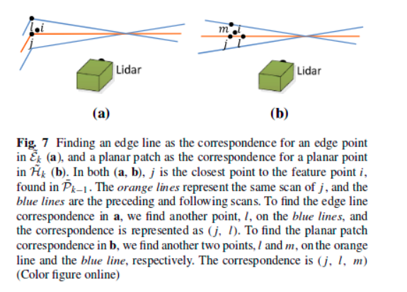
找t+1时刻的某个特征边/面上的点在t时刻下对应的配准点,论文作者给出如上图的思路。特征线:利用KD树找点i在t时刻点云中最近的一点j,并在j周围(上下几条线的范围内)找次近点l,于是我们把(j,l)称为点i在t时刻点云中的对应。特征面:与特征线类似,先找最近点j,在j周围找l,在j周围找m,将(j,l,m)称为点i在t时刻点云中的对应。代码实现如下:
特征线:
TransformToStart(&cornerPointsSharp->points[i], &pointSel);
// 将点坐标转换到起始点云坐标系中
// 每迭代五次,搜索一次最近点和次临近点(降采样)
if (iterCount % 5 == 0) {
std::vector<int> indices;
pcl::removeNaNFromPointCloud(*laserCloudCornerLast,*laserCloudCornerLast, indices);
// 找到pointSel(当前时刻边特征中的某一点)在laserCloudCornerLast中的1个最邻近点
// -> 返回pointSearchInd(点对应的索引) pointSearchSqDis(pointSel与对应点的欧氏距离)
kdtreeCornerLast->nearestKSearch(pointSel, 1, pointSearchInd, pointSearchSqDis);
/***** 在最邻近点附近(向上下三条扫描线以内)找到次临近点 *****/
int closestPointInd = -1, minPointInd2 = -1;
if (pointSearchSqDis[0] < 25) {
int closestPointScan = int(laserCloudCornerLast->points[closestPointInd].intensity); // 搜索到的点所在线数
float pointSqDis, minPointSqDis2 = 25;
// 从找得到的最邻近点开始,遍历所有边特征点
for (int j = closestPointInd + 1; j < cornerPointsSharpNum; j++) {
// 找到与最邻近点相距3条线的特征点时跳出
if (int(laserCloudCornerLast->points[j].intensity) > closestPointScan + 2.5) {
break;
}
// 计算遍历点与最邻近点的距离(平方)
pointSqDis = (laserCloudCornerLast->points[j].x - pointSel.x) *
(laserCloudCornerLast->points[j].x - pointSel.x) +
(laserCloudCornerLast->points[j].y - pointSel.y) *
(laserCloudCornerLast->points[j].y - pointSel.y) +
(laserCloudCornerLast->points[j].z - pointSel.z) *
(laserCloudCornerLast->points[j].z - pointSel.z);
if (int(laserCloudCornerLast->points[j].intensity) > closestPointScan) {
if (pointSqDis < minPointSqDis2) {
minPointSqDis2 = pointSqDis;
minPointInd2 = j;
}
}
}
// 向下三条线,找次临近点
for (int j = closestPointInd - 1; j >= 0; j--) {
if (int(laserCloudCornerLast->points[j].intensity) < closestPointScan - 2.5) {
break;
}
pointSqDis = (laserCloudCornerLast->points[j].x - pointSel.x) *
(laserCloudCornerLast->points[j].x - pointSel.x) +
(laserCloudCornerLast->points[j].y - pointSel.y) *
(laserCloudCornerLast->points[j].y - pointSel.y) +
(laserCloudCornerLast->points[j].z - pointSel.z) *
(laserCloudCornerLast->points[j].z - pointSel.z);
if (int(laserCloudCornerLast->points[j].intensity) < closestPointScan) {
if (pointSqDis < minPointSqDis2) {
minPointSqDis2 = pointSqDis;
minPointInd2 = j;
}
}
}
}
/*********************************************/
pointSearchCornerInd1[i] = closestPointInd; // 当前所有边特征点在上一时刻边特征点云中对应的最邻近点的索引
pointSearchCornerInd2[i] = minPointInd2; // 当前所有边特征点在上一时刻边特征点云中对应的次邻近点的索引
}
特征面:
TransformToStart(&surfPointsFlat->points[i], &pointSel);
if (iterCount % 5 == 0) {
kdtreeSurfLast->nearestKSearch(pointSel, 1, pointSearchInd, pointSearchSqDis);
int closestPointInd = -1, minPointInd2 = -1, minPointInd3 = -1;
if (pointSearchSqDis[0] < 25) {
closestPointInd = pointSearchInd[0];
int closestPointScan = int(laserCloudSurfLast->points[closestPointInd].intensity);
float pointSqDis, minPointSqDis2 = 25, minPointSqDis3 = 25;
for (int j = closestPointInd + 1; j < surfPointsFlatNum; j++) {
if (int(laserCloudSurfLast->points[j].intensity) > closestPointScan + 2.5) {
break;
}
pointSqDis = (laserCloudSurfLast->points[j].x - pointSel.x) *
(laserCloudSurfLast->points[j].x - pointSel.x) +
(laserCloudSurfLast->points[j].y - pointSel.y) *
(laserCloudSurfLast->points[j].y - pointSel.y) +
(laserCloudSurfLast->points[j].z - pointSel.z) *
(laserCloudSurfLast->points[j].z - pointSel.z);
if (int(laserCloudSurfLast->points[j].intensity) <= closestPointScan) {
if (pointSqDis < minPointSqDis2) {
minPointSqDis2 = pointSqDis;
minPointInd2 = j;
}
} else {
if (pointSqDis < minPointSqDis3) {
minPointSqDis3 = pointSqDis;
minPointInd3 = j;
}
}
}
for (int j = closestPointInd - 1; j >= 0; j--) {
if (int(laserCloudSurfLast->points[j].intensity) < closestPointScan - 2.5) {
break;
}
pointSqDis = (laserCloudSurfLast->points[j].x - pointSel.x) *
(laserCloudSurfLast->points[j].x - pointSel.x) +
(laserCloudSurfLast->points[j].y - pointSel.y) *
(laserCloudSurfLast->points[j].y - pointSel.y) +
(laserCloudSurfLast->points[j].z - pointSel.z) *
(laserCloudSurfLast->points[j].z - pointSel.z);
if (int(laserCloudSurfLast->points[j].intensity) >= closestPointScan) {
if (pointSqDis < minPointSqDis2) {
minPointSqDis2 = pointSqDis;
minPointInd2 = j;
}
} else {
if (pointSqDis < minPointSqDis3) {
minPointSqDis3 = pointSqDis;
minPointInd3 = j;
}
}
}
}
pointSearchSurfInd1[i] = closestPointInd;
pointSearchSurfInd2[i] = minPointInd2;
pointSearchSurfInd3[i] = minPointInd3;
}
这里需要指出的是:并不是每次运动估计完成一次迭代,就进行一次坐标转换,然后在整个点云范围内搜索其最近点。这里设定了一个5次的阈值,每五次搜索一次,以保证运行效率。
构建Jaccobian矩阵
我们之所以去找配准点,目的在于找到不同时刻的两帧点云间的约束关系。那么他们之间有什么约束关系呢?作者分别给了关于线和面的两个约束方程:
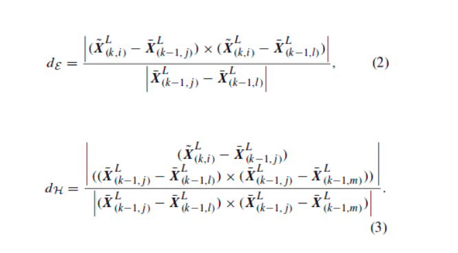
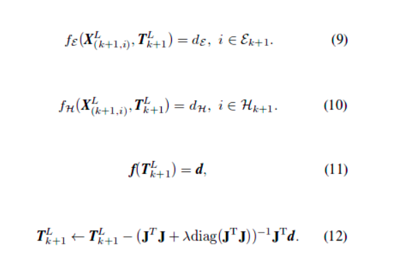
根据公式(2)-(3)我们有了这两帧点云的约束方程,构建Jaccobian矩阵就非常简单了,直接对待估参数( X~(k,i)L )求偏导就ok了。再看对应程序中如何实现偏导的:
特征线:
if (pointSearchCornerInd2[i] >= 0) {
tripod1 = laserCloudCornerLast->points[pointSearchCornerInd1[i]]; // 最邻近点
tripod2 = laserCloudCornerLast->points[pointSearchCornerInd2[i]]; // 次临近点
// 当前点云的点坐标
float x0 = pointSel.x;
float y0 = pointSel.y;
float z0 = pointSel.z;
// 上一时刻最邻近点的点坐标
float x1 = tripod1.x;
float y1 = tripod1.y;
float z1 = tripod1.z;
// 上一时刻次临近点的点坐标
float x2 = tripod2.x;
float y2 = tripod2.y;
float z2 = tripod2.z;
// 文章中公式(2)的分子部分->分别作差并叉乘后的向量模长
float a012 = sqrt(((x0 - x1)*(y0 - y2) - (x0 - x2)*(y0 - y1))
* ((x0 - x1)*(y0 - y2) - (x0 - x2)*(y0 - y1))
+ ((x0 - x1)*(z0 - z2) - (x0 - x2)*(z0 - z1))
* ((x0 - x1)*(z0 - z2) - (x0 - x2)*(z0 - z1))
+ ((y0 - y1)*(z0 - z2) - (y0 - y2)*(z0 - z1))
* ((y0 - y1)*(z0 - z2) - (y0 - y2)*(z0 - z1)));
// 文章中公式(2)分母部分 -> 两点间距离
float l12 = sqrt((x1 - x2)*(x1 - x2) + (y1 - y2)*(y1 - y2) + (z1 - z2)*(z1 - z2));
// 向量[la;lb;lc] 为距离ld2分别对x0 y0 z0的偏导
float la = ((y1 - y2)*((x0 - x1)*(y0 - y2) - (x0 - x2)*(y0 - y1))
+ (z1 - z2)*((x0 - x1)*(z0 - z2) - (x0 - x2)*(z0 - z1))) / a012 / l12;
float lb = -((x1 - x2)*((x0 - x1)*(y0 - y2) - (x0 - x2)*(y0 - y1))
- (z1 - z2)*((y0 - y1)*(z0 - z2) - (y0 - y2)*(z0 - z1))) / a012 / l12;
float lc = -((x1 - x2)*((x0 - x1)*(z0 - z2) - (x0 - x2)*(z0 - z1))
+ (y1 - y2)*((y0 - y1)*(z0 - z2) - (y0 - y2)*(z0 - z1))) / a012 / l12;
float ld2 = a012 / l12;
pointProj = pointSel;
pointProj.x -= la * ld2;
pointProj.y -= lb * ld2;
pointProj.z -= lc * ld2;
float s = 1; // 阻尼因子
if (iterCount >= 5) {
// 点到直线距离越小阻尼因子越大
s = 1 - 1.8 * fabs(ld2);
}
coeff.x = s * la;
coeff.y = s * lb;
coeff.z = s * lc;
coeff.intensity = s * ld2;
// 满足阈值(ld2 < 0.5),将特征点插入
if (s > 0.1 && ld2 != 0) {
laserCloudOri->push_back(cornerPointsSharp->points[i]);
coeffSel->push_back(coeff);
}
}
特征面:
if (pointSearchSurfInd2[i] >= 0 && pointSearchSurfInd3[i] >= 0) {
tripod1 = laserCloudSurfLast->points[pointSearchSurfInd1[i]];
tripod2 = laserCloudSurfLast->points[pointSearchSurfInd2[i]];
tripod3 = laserCloudSurfLast->points[pointSearchSurfInd3[i]];
// 向量[pa;pb;pc] = 点到面的距离对x0 y0 z0的偏导
float pa = (tripod2.y - tripod1.y) * (tripod3.z - tripod1.z)
- (tripod3.y - tripod1.y) * (tripod2.z - tripod1.z);
float pb = (tripod2.z - tripod1.z) * (tripod3.x - tripod1.x)
- (tripod3.z - tripod1.z) * (tripod2.x - tripod1.x);
float pc = (tripod2.x - tripod1.x) * (tripod3.y - tripod1.y)
- (tripod3.x - tripod1.x) * (tripod2.y - tripod1.y);
float pd = -(pa * tripod1.x + pb * tripod1.y + pc * tripod1.z);
float ps = sqrt(pa * pa + pb * pb + pc * pc);
pa /= ps;
pb /= ps;
pc /= ps;
pd /= ps;
float pd2 = pa * pointSel.x + pb * pointSel.y + pc * pointSel.z + pd;
pointProj = pointSel;
pointProj.x -= pa * pd2;
pointProj.y -= pb * pd2;
pointProj.z -= pc * pd2;
float s = 1;
if (iterCount >= 5) {
s = 1 - 1.8 * fabs(pd2) / sqrt(sqrt(pointSel.x * pointSel.x
+ pointSel.y * pointSel.y + pointSel.z * pointSel.z));
}
coeff.x = s * pa;
coeff.y = s * pb;
coeff.z = s * pc;
coeff.intensity = s * pd2;
if (s > 0.1 && pd2 != 0) {
laserCloudOri->push_back(surfPointsFlat->points[i]);
coeffSel->push_back(coeff);
}
}
至此Jaccobian矩阵就构建完毕了。每个特征点对应的Jaccobian矩阵的三个元素都保存在coeffSel中,后面采用L-M方法解算的时候直接调用就行了。
L-M运动估计求解
解算前首先要搞清楚要怎么表达Lidar的姿态,论文中给出公式:
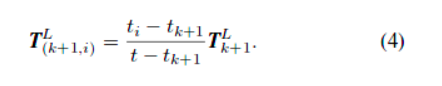
我们认为Lidar匀速运动,因此公式(4)实现了Lidar变换矩阵的内插,得到其扫描点i时刻的位姿
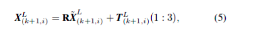
公式(5)就是经典的刚体的旋转平移变换。
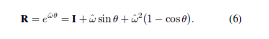
公式(6)为罗德里格斯公式,将旋转矩阵用旋转矢量表示,这种方法的最大优势在于节约计算所消耗的资源。
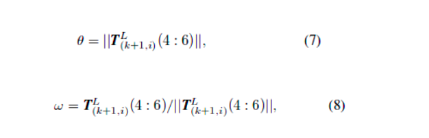
公式(7)-(8)分别为旋转矢量公式中的参数计算。搞清楚这些以后,就开始L-M的计算了;
这就是LM的解算过程,具体程序实现:
int pointSelNum = laserCloudOri->points.size(); // 匹配到的点的个数(即存在多少个约束)
if (pointSelNum < 10) {
continue;
}
cv::Mat matA(pointSelNum, 6, CV_32F, cv::Scalar::all(0));
cv::Mat matAt(6, pointSelNum, CV_32F, cv::Scalar::all(0));
cv::Mat matAtA(6, 6, CV_32F, cv::Scalar::all(0));
cv::Mat matB(pointSelNum, 1, CV_32F, cv::Scalar::all(0));
cv::Mat matAtB(6, 1, CV_32F, cv::Scalar::all(0));
cv::Mat matX(6, 1, CV_32F, cv::Scalar::all(0));
// 构建Jaccobian矩阵
for (int i = 0; i < pointSelNum; i++) {
/**
* 采用Levenberg-Marquardt计算
* 首先建立当前时刻Lidar坐标系下提取到的特征点与点到直线/平面
* 的约束方程。而后对约束方程求对坐标变换(3旋转+3平移)的偏导
* 公式参见论文(2)-(8)
*/
pointOri = laserCloudOri->points[i]; // 当前时刻点坐标
coeff = coeffSel->points[i]; // 该点所对应的偏导数
float s = 1;
float srx = sin(s * transform[0]);
float crx = cos(s * transform[0]);
float sry = sin(s * transform[1]);
float cry = cos(s * transform[1]);
float srz = sin(s * transform[2]);
float crz = cos(s * transform[2]);
float tx = s * transform[3];
float ty = s * transform[4];
float tz = s * transform[5];
float arx = (-s*crx*sry*srz*pointOri.x + s*crx*crz*sry*pointOri.y + s*srx*sry*pointOri.z
+ s*tx*crx*sry*srz - s*ty*crx*crz*sry - s*tz*srx*sry) * coeff.x
+ (s*srx*srz*pointOri.x - s*crz*srx*pointOri.y + s*crx*pointOri.z
+ s*ty*crz*srx - s*tz*crx - s*tx*srx*srz) * coeff.y
+ (s*crx*cry*srz*pointOri.x - s*crx*cry*crz*pointOri.y - s*cry*srx*pointOri.z
+ s*tz*cry*srx + s*ty*crx*cry*crz - s*tx*crx*cry*srz) * coeff.z;
float ary = ((-s*crz*sry - s*cry*srx*srz)*pointOri.x
+ (s*cry*crz*srx - s*sry*srz)*pointOri.y - s*crx*cry*pointOri.z
+ tx*(s*crz*sry + s*cry*srx*srz) + ty*(s*sry*srz - s*cry*crz*srx)
+ s*tz*crx*cry) * coeff.x
+ ((s*cry*crz - s*srx*sry*srz)*pointOri.x
+ (s*cry*srz + s*crz*srx*sry)*pointOri.y - s*crx*sry*pointOri.z
+ s*tz*crx*sry - ty*(s*cry*srz + s*crz*srx*sry)
- tx*(s*cry*crz - s*srx*sry*srz)) * coeff.z;
float arz = ((-s*cry*srz - s*crz*srx*sry)*pointOri.x + (s*cry*crz - s*srx*sry*srz)*pointOri.y
+ tx*(s*cry*srz + s*crz*srx*sry) - ty*(s*cry*crz - s*srx*sry*srz)) * coeff.x
+ (-s*crx*crz*pointOri.x - s*crx*srz*pointOri.y
+ s*ty*crx*srz + s*tx*crx*crz) * coeff.y
+ ((s*cry*crz*srx - s*sry*srz)*pointOri.x + (s*crz*sry + s*cry*srx*srz)*pointOri.y
+ tx*(s*sry*srz - s*cry*crz*srx) - ty*(s*crz*sry + s*cry*srx*srz)) * coeff.z;
float atx = -s*(cry*crz - srx*sry*srz) * coeff.x + s*crx*srz * coeff.y
- s*(crz*sry + cry*srx*srz) * coeff.z;
float aty = -s*(cry*srz + crz*srx*sry) * coeff.x - s*crx*crz * coeff.y
- s*(sry*srz - cry*crz*srx) * coeff.z;
float atz = s*crx*sry * coeff.x - s*srx * coeff.y - s*crx*cry * coeff.z;
float d2 = coeff.intensity;
matA.at<float>(i, 0) = arx;
matA.at<float>(i, 1) = ary;
matA.at<float>(i, 2) = arz;
matA.at<float>(i, 3) = atx;
matA.at<float>(i, 4) = aty;
matA.at<float>(i, 5) = atz;
matB.at<float>(i, 0) = -0.05 * d2;
}
// 最小二乘计算(QR分解法)
cv::transpose(matA, matAt);
matAtA = matAt * matA;
matAtB = matAt * matB;
cv::solve(matAtA, matAtB, matX, cv::DECOMP_QR);
if (iterCount == 0) {
cv::Mat matE(1, 6, CV_32F, cv::Scalar::all(0));
cv::Mat matV(6, 6, CV_32F, cv::Scalar::all(0));
cv::Mat matV2(6, 6, CV_32F, cv::Scalar::all(0));
cv::eigen(matAtA, matE, matV); // 计算矩阵的特征向量E及特征向量的反对称阵V
matV.copyTo(matV2);
isDegenerate = false;
float eignThre[6] = {10, 10, 10, 10, 10, 10};
for (int i = 5; i >= 0; i--) {
if (matE.at<float>(0, i) < eignThre[i]) {
for (int j = 0; j < 6; j++) {
matV2.at<float>(i, j) = 0;
}
isDegenerate = true; // 存在比10小的特征值则出现退化
} else {
break;
}
}
matP = matV.inv() * matV2;
}
if (isDegenerate) {
cv::Mat matX2(6, 1, CV_32F, cv::Scalar::all(0));
matX.copyTo(matX2);
matX = matP * matX2;
}
transform[0] += matX.at<float>(0, 0);
transform[1] += matX.at<float>(1, 0);
transform[2] += matX.at<float>(2, 0);
transform[3] += matX.at<float>(3, 0);
transform[4] += matX.at<float>(4, 0);
transform[5] += matX.at<float>(5, 0);
for(int i=0; i<6; i++){
if(isnan(transform[i]))
transform[i]=0;
}
float deltaR = sqrt(
pow(rad2deg(matX.at<float>(0, 0)), 2) +
pow(rad2deg(matX.at<float>(1, 0)), 2) +
pow(rad2deg(matX.at<float>(2, 0)), 2));
float deltaT = sqrt(
pow(matX.at<float>(3, 0) * 100, 2) +
pow(matX.at<float>(4, 0) * 100, 2) +
pow(matX.at<float>(5, 0) * 100, 2));
if (deltaR < 0.1 && deltaT < 0.1) {
break;
}
/*************************************************/
对这种最小二成解算方法比较熟悉的同学应该能很容易看懂,中间各种求偏导数的公式我就不推了,有兴趣的可以自己推一推。
3. 坐标转换
算出了两帧点云间的相对运动,但他们是在这两帧点云的局部坐标系下的,我们需要把它转换到世界坐标系下,因此需要进行转换。这部分内容较为简单,直接上代码了:
float rx, ry, rz, tx, ty, tz;
// 计算旋转角的累计变化量
AccumulateRotation(transformSum[0], transformSum[1], transformSum[2],
-transform[0], -transform[1] * 1.05, -transform[2], rx, ry, rz);
float x1 = cos(rz) * (transform[3] - imuShiftFromStartX)
- sin(rz) * (transform[4] - imuShiftFromStartY);
float y1 = sin(rz) * (transform[3] - imuShiftFromStartX)
+ cos(rz) * (transform[4] - imuShiftFromStartY);
float z1 = transform[5] * 1.05 - imuShiftFromStartZ;
float x2 = x1;
float y2 = cos(rx) * y1 - sin(rx) * z1;
float z2 = sin(rx) * y1 + cos(rx) * z1;
tx = transformSum[3] - (cos(ry) * x2 + sin(ry) * z2);
ty = transformSum[4] - y2;
tz = transformSum[5] - (-sin(ry) * x2 + cos(ry) * z2);
PluginIMURotation(rx, ry, rz, imuPitchStart, imuYawStart, imuRollStart,
imuPitchLast, imuYawLast, imuRollLast, rx, ry, rz);
transformSum[0] = rx;
transformSum[1] = ry;
transformSum[2] = rz;
transformSum[3] = tx;
transformSum[4] = ty;
transformSum[5] = tz;
geometry_msgs::Quaternion geoQuat = tf::createQuaternionMsgFromRollPitchYaw(rz, -rx, -ry); // 该函数定义的坐标系与本程序所定义的不同,因此取负号
laserOdometry.header.stamp = ros::Time().fromSec(timeSurfPointsLessFlat);
laserOdometry.pose.pose.orientation.x = -geoQuat.y;
laserOdometry.pose.pose.orientation.y = -geoQuat.z;
laserOdometry.pose.pose.orientation.z = geoQuat.x;
laserOdometry.pose.pose.orientation.w = geoQuat.w;
laserOdometry.pose.pose.position.x = tx;
laserOdometry.pose.pose.position.y = ty;
laserOdometry.pose.pose.position.z = tz;
pubLaserOdometry.publish(laserOdometry);
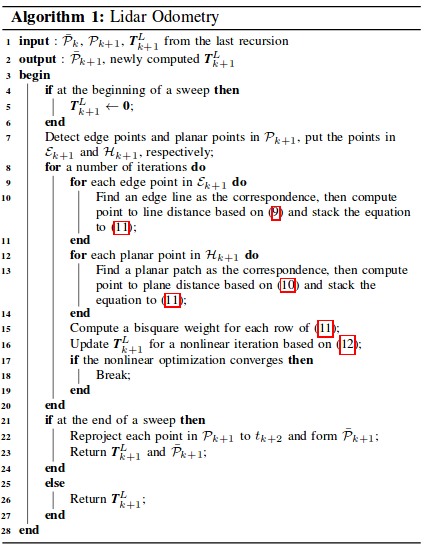
至此我们接完成了整个laserOdometry的计算,剩下的只需要把这些计算结果发布出去就好了。最后贴一张论文里这块内容的伪码图帮助大家更好的理解这块内容的一个框架:
第三部分:laserMapping.cpp
LOAM中的laserMapping节点进行深入解析
先来梳理一下:点云数据进来后,经过前两个节点的处理可以完成一个完整但粗糙的视觉里程计,可以概略地估计出Lidar的相对运动。如果不受任何测量噪声的影响,这个运动估计的结果足够精确,没有任何漂移,那我们可以直接利用估计的Lidar位姿和对应时刻的量测值完成建图。但这就如同现实中不存在一个不受外力就能匀速直线运动的小球一样,量测噪声是不可避免的,因此Lidar位姿估计偏差一定存在。
为了搞懂这部分内容,首先有两个问题需要明确:
- 为什么要有这个建图节点?
- 建图节点又到底起了什么作用?
先来回答第一个问题:为什么要有建图节点。正如我们刚才所说,Lidar里程计的结果不准确,拼起来的点也完全不成样子,且它会不断发散,因此误差也会越来越大。试想一下我们对特征的提取仅仅只是关注了他们的曲率,这种方式怎么可能完美的得到两帧点云准确的配准点。且点云中的点是离散的,我们也无法保证上一帧的点在下一帧中仍会被扫到。总之,无论我们多努力想让Lidar里程计的估计结果变得精准,残酷且冰冷的显示都会把我们的幻想击碎。因此,我们需要依靠别的方式去优化Lidar里程计的位姿估计精度。在SLAM领域,一般会采用与地图匹配的方式来优化这一结果。其实道理也很简单,我们始终认为后一时刻的观测较前一时刻带有更多的误差,换而言之,我们更加信任前一时刻结果。因此我们对已经构建地图的信任程度远高于临帧点云配准后的Lidar运动估计。所以我们可以利用已构建地图对位姿估计结果进行修正。
第二个问题:建图节点起到了什么作用?在回答上一个问题时也已经提到了,它的作用就是优化Lidar里程计的位姿估计结果。怎么做呢?没错,就是利用地图。试想一下,你在得到第一帧点云时你的lidar就扫到了数万个点,此时Lidar的位置我们把它作为(0,0,0),在不考虑测量噪声的情况下这数万个点都是相对精确的,我们把这数万个点所构成的环境作为此时的地图。而后Lidar运动了一小段,我们通过Lidar里程计的方法估算了它的相对运动,于是就可以将此时的Lidar位姿及此时的点按照我们估计的相对运动情况,转换到上一时刻(建立地图时的坐标系)的坐标系下。只不过由于里程计估计误差,地图可能拼歪了。既然这样,我是如果把地图完整的拼上去,是不是就可以优化此时Lidar的位姿了呢?这就是建图节点起到的关键作用。只不过拿当前扫描的点云和地图中所有点云去配准,这个计算消耗太大,因此为了保证实时性,作者在这里采用了一种低频处理方法,即调用建图节点的频率仅为调用里程计节点频率的十分之一。
这块内容的整体思路还是很简单的,但实现起来还是要费一些功夫。前面依旧时ROS的套路代码,就不贴了,看不懂的可以参考之前的。代码的整体框架长这个样子:在订阅器订阅到了laserOdometry发布的消息后即可开始进行处理。
int frameCount = stackFrameNum - 1; // initialize as 0
int mapFrameCount = mapFrameNum - 1; // initialize as 4
ros::Rate rate(100);
bool status = ros::ok();
while (status) {
ros::spinOnce();
if (newLaserCloudCornerLast && newLaserCloudSurfLast && newLaserCloudFullRes && newLaserOdometry &&
fabs(timeLaserCloudCornerLast - timeLaserOdometry) < 0.005 &&
fabs(timeLaserCloudSurfLast - timeLaserOdometry) < 0.005 &&
fabs(timeLaserCloudFullRes - timeLaserOdometry) < 0.005) {
newLaserCloudCornerLast = false;
newLaserCloudSurfLast = false;
newLaserCloudFullRes = false;
newLaserOdometry = false;
frameCount++;
/***** 坐标转换 *****/
if (frameCount >= stackFrameNum) {
}
/***** 优化处理 *****/
if (frameCount >= stackFrameNum) {
}
status = ros::ok();
rate.sleep();
}
坐标转换
这部分十分清晰,是点云数据处理前的准备工作。首先计算 而后根据
而后根据 将测量得到的点坐标转换到世界坐标系{W}下。两个坐标转换函数都采用欧拉角表示姿态旋转
// 将相关坐标转移到世界坐标系下->得到可用于建图的Lidar坐标
transformAssociateToMap();
// 将上一时刻所有边特征转到世界坐标系下
int laserCloudCornerLastNum = laserCloudCornerLast->points.size();
for (int i = 0; i < laserCloudCornerLastNum; i++) {
pointAssociateToMap(&laserCloudCornerLast->points[i], &pointSel);
laserCloudCornerStack2->push_back(pointSel);
}
// 将上一时刻所有面特征转到世界坐标系下
int laserCloudSurfLastNum = laserCloudSurfLast->points.size();
for (int i = 0; i < laserCloudSurfLastNum; i++) {
pointAssociateToMap(&laserCloudSurfLast->points[i], &pointSel);
laserCloudSurfStack2->push_back(pointSel);
}
优化处理
将地图 Qk−1 保存在一个10m的立方体中,若cube中的点与当前帧中的点云 Q¯k 有重叠部分就把他们提取出来保存在KD树中。我们找地图 Qk−1 中的点时,要在特征点附近宽为10cm的立方体邻域内搜索(实际代码中是10cm×10cm×5cm)。
虽然就这么两句话,但是要用一大堆代码坑去填啊。实际处理中,我们首先将地图点云 Qk−1 保存在一个大cube中,并将其分割为一些子cube。
int laserCloudCenWidth = 10; // 邻域宽度, cm为单位
int laserCloudCenHeight = 5; // 邻域高度
int laserCloudCenDepth = 10; // 邻域深度
const int laserCloudWidth = 21; // 子cube沿宽方向的分割个数
const int laserCloudHeight = 11; // 高方向个数
const int laserCloudDepth = 21; // 深度方向个数
const int laserCloudNum = laserCloudWidth * laserCloudHeight * laserCloudDepth; // 子cube总数
而后我们就要找当前估计的Lidar位姿  属于哪个子cube。I、J、K对应了cube的索引。可以看出,当坐标属于[-25,25]时,cube对应与(10,5,10)即正中心的那个cube。
PointType pointOnYAxis; // 当前Lidar坐标系{L}y轴上的一点(0,10,0)
pointOnYAxis.x = 0.0;
pointOnYAxis.y = 10.0;
pointOnYAxis.z = 0.0;
pointAssociateToMap(&pointOnYAxis, &pointOnYAxis); // 转到世界坐标系{W}下
// cube中心位置索引
int centerCubeI = int((transformTobeMapped[3] + 25.0) / 50.0) + laserCloudCenWidth;
int centerCubeJ = int((transformTobeMapped[4] + 25.0) / 50.0) + laserCloudCenHeight;
int centerCubeK = int((transformTobeMapped[5] + 25.0) / 50.0) + laserCloudCenDepth;
if (transformTobeMapped[3] + 25.0 < 0) centerCubeI--;
if (transformTobeMapped[4] + 25.0 < 0) centerCubeJ--;
if (transformTobeMapped[5] + 25.0 < 0) centerCubeK--;
如果取到的子cube在整个大cube的边缘则将点对应的cube的索引向中心方向挪动一个单位,这样做主要是截取边沿cube。
while (centerCubeI < 3) {
// 将点的指针向中心方向平移
for (int j = 0; j < laserCloudHeight; j++) {
for (int k = 0; k < laserCloudDepth; k++) {
int i = laserCloudWidth - 1;
pcl::PointCloud<PointType>::Ptr laserCloudCubeCornerPointer =
laserCloudCornerArray[i + laserCloudWidth * j + laserCloudWidth * laserCloudHeight * k];
pcl::PointCloud<PointType>::Ptr laserCloudCubeSurfPointer =
laserCloudSurfArray[i + laserCloudWidth * j + laserCloudWidth * laserCloudHeight * k];
for (; i >= 1; i--) {
laserCloudCornerArray[i + laserCloudWidth * j + laserCloudWidth * laserCloudHeight * k] =
laserCloudCornerArray[i - 1 + laserCloudWidth*j + laserCloudWidth * laserCloudHeight * k];
laserCloudSurfArray[i + laserCloudWidth * j + laserCloudWidth * laserCloudHeight * k] =
laserCloudSurfArray[i - 1 + laserCloudWidth * j + laserCloudWidth * laserCloudHeight * k];
}
laserCloudCornerArray[i + laserCloudWidth * j + laserCloudWidth * laserCloudHeight * k] =
laserCloudCubeCornerPointer;
laserCloudSurfArray[i + laserCloudWidth * j + laserCloudWidth * laserCloudHeight * k] =
laserCloudCubeSurfPointer;
laserCloudCubeCornerPointer->clear();
laserCloudCubeSurfPointer->clear();
}
}
// 对应索引加1
centerCubeI++;
laserCloudCenWidth++;
}
while (centerCubeI >= laserCloudWidth - 3) {
// 将点的指针向中心方向平移
for (int j = 0; j < laserCloudHeight; j++) {
for (int k = 0; k < laserCloudDepth; k++) {
int i = 0;
pcl::PointCloud<PointType>::Ptr laserCloudCubeCornerPointer =
laserCloudCornerArray[i + laserCloudWidth * j + laserCloudWidth * laserCloudHeight * k];
pcl::PointCloud<PointType>::Ptr laserCloudCubeSurfPointer =
laserCloudSurfArray[i + laserCloudWidth * j + laserCloudWidth * laserCloudHeight * k];
for (; i < laserCloudWidth - 1; i++) {
laserCloudCornerArray[i + laserCloudWidth * j + laserCloudWidth * laserCloudHeight * k] =
laserCloudCornerArray[i + 1 + laserCloudWidth*j + laserCloudWidth * laserCloudHeight * k];
laserCloudSurfArray[i + laserCloudWidth * j + laserCloudWidth * laserCloudHeight * k] =
laserCloudSurfArray[i + 1 + laserCloudWidth * j + laserCloudWidth * laserCloudHeight * k];
}
laserCloudCornerArray[i + laserCloudWidth * j + laserCloudWidth * laserCloudHeight * k] =
laserCloudCubeCornerPointer;
laserCloudSurfArray[i + laserCloudWidth * j + laserCloudWidth * laserCloudHeight * k] =
laserCloudCubeSurfPointer;
laserCloudCubeCornerPointer->clear();
laserCloudCubeSurfPointer->clear();
}
}
centerCubeI--;
laserCloudCenWidth--;
}
处理完毕边沿点,接下来就是在取到的子cube的5*5*5的邻域内找对应的配准点了。
int laserCloudValidNum = 0;
int laserCloudSurroundNum = 0;
for (int i = centerCubeI - 2; i <= centerCubeI + 2; i++) {
for (int j = centerCubeJ - 2; j <= centerCubeJ + 2; j++) {
for (int k = centerCubeK - 2; k <= centerCubeK + 2; k++) {
if (i >= 0 && i < laserCloudWidth &&
j >= 0 && j < laserCloudHeight &&
k >= 0 && k < laserCloudDepth) {
// 计算子cube对应的点坐标
// NOTE: 由于ijk均为整数,坐标取值为中心点坐标
float centerX = 50.0 * (i - laserCloudCenWidth);
float centerY = 50.0 * (j - laserCloudCenHeight);
float centerZ = 50.0 * (k - laserCloudCenDepth);
// 取邻近的8个点坐标
bool isInLaserFOV = false;
for (int ii = -1; ii <= 1; ii += 2) {
for (int jj = -1; jj <= 1; jj += 2) {
for (int kk = -1; kk <= 1; kk += 2) {
float cornerX = centerX + 25.0 * ii;
float cornerY = centerY + 25.0 * jj;
float cornerZ = centerZ + 25.0 * kk;
float squaredSide1 = (transformTobeMapped[3] - cornerX)
* (transformTobeMapped[3] - cornerX)
+ (transformTobeMapped[4] - cornerY)
* (transformTobeMapped[4] - cornerY)
+ (transformTobeMapped[5] - cornerZ)
* (transformTobeMapped[5] - cornerZ);
float squaredSide2 = (pointOnYAxis.x - cornerX) * (pointOnYAxis.x - cornerX)
+ (pointOnYAxis.y - cornerY) * (pointOnYAxis.y - cornerY)
+ (pointOnYAxis.z - cornerZ) * (pointOnYAxis.z - cornerZ);
float check1 = 100.0 + squaredSide1 - squaredSide2
- 10.0 * sqrt(3.0) * sqrt(squaredSide1);
float check2 = 100.0 + squaredSide1 - squaredSide2
+ 10.0 * sqrt(3.0) * sqrt(squaredSide1);
if (check1 < 0 && check2 > 0) {
isInLaserFOV = true;
}
}
}
}
if (isInLaserFOV) {
laserCloudValidInd[laserCloudValidNum] = i + laserCloudWidth * j
+ laserCloudWidth * laserCloudHeight * k;
laserCloudValidNum++;
}
laserCloudSurroundInd[laserCloudSurroundNum] = i + laserCloudWidth * j
+ laserCloudWidth * laserCloudHeight * k;
laserCloudSurroundNum++;
}
}
}
}
这里还需要判断一下该点是否属于当前Lidar的可视范围内,可以根据余弦公式对距离范围进行推导。根据代码中的式子,只要点在x轴±60°的范围内都认为是FOV中的点(作者这么做是因为Lidar里程计的估计结果抬不准确了,只能概略的取一个较大的范围)。于是我们就得到了在当前Lidar位置的邻域内有效的地图特征点。
所以,我们就不需要对庞大的所有地图点云进行处理了,只需要处理这些邻域cube内的地图特征点即可,可以节省大量的运算资源。为了保证当前帧的点云足够平滑,还对点云进行了滤波处理。
laserCloudCornerFromMap->clear();
laserCloudSurfFromMap->clear();
for (int i = 0; i < laserCloudValidNum; i++) {
*laserCloudCornerFromMap += *laserCloudCornerArray[laserCloudValidInd[i]];
*laserCloudSurfFromMap += *laserCloudSurfArray[laserCloudValidInd[i]];
}
int laserCloudCornerFromMapNum = laserCloudCornerFromMap->points.size(); // 有效的特征边上的点的个数
int laserCloudSurfFromMapNum = laserCloudSurfFromMap->points.size(); // 有效的特征面上的点的个数
// 将世界坐标系下的当前帧特征点转到当前Lidar坐标系下
int laserCloudCornerStackNum2 = laserCloudCornerStack2->points.size(); // 所有特征边上的点的个数
for (int i = 0; i < laserCloudCornerStackNum2; i++) {
pointAssociateTobeMapped(&laserCloudCornerStack2->points[i], &laserCloudCornerStack2->points[i]);
}
int laserCloudSurfStackNum2 = laserCloudSurfStack2->points.size(); // 所有特征面上的点的个数
for (int i = 0; i < laserCloudSurfStackNum2; i++) {
pointAssociateTobeMapped(&laserCloudSurfStack2->points[i], &laserCloudSurfStack2->points[i]);
}
// 对所有当前帧特征点进行滤波处理
laserCloudCornerStack->clear();
downSizeFilterCorner.setInputCloud(laserCloudCornerStack2);
downSizeFilterCorner.filter(*laserCloudCornerStack);
int laserCloudCornerStackNum = laserCloudCornerStack->points.size();
laserCloudSurfStack->clear();
downSizeFilterSurf.setInputCloud(laserCloudSurfStack2);
downSizeFilterSurf.filter(*laserCloudSurfStack);
int laserCloudSurfStackNum = laserCloudSurfStack->points.size();
laserCloudCornerStack2->clear();
laserCloudSurfStack2->clear();
做完这些工作以后,我们就有了在当前Lidar所在位置附近的所有地图特征点以及当前帧的点云特征点,后面的工作就是怎么把这两坨点匹配在一起啦!于是我们再次拿出KD树,来寻找最邻近的5个点。对点云协方差矩阵进行主成分分析:若这五个点分布在直线上,协方差矩阵的特征值包含一个元素显著大于其余两个,与该特征值相关的特征向量表示所处直线的方向;若这五个点分布在平面上,协方差矩阵的特征值存在一个显著小的元素,与该特征值相关的特征向量表示所处平面的法线方向。因此我们可以很轻易的根据特征向量找到直线上两点从而利用论文中点到直线的距离公式构建优化问题(对优化问题有疑问的同学请参考上面)。平面特征也是相同的思路。完成了优化问题的构建之后就可以对它进行求解了,求解方法还是L-M迭代。这部分代码与laserOdometry部分的几乎一致,我就不贴了。
截止到这里,我们就完成了当前帧点云与地图点云的配准,并对Lidar里程计的运动估计结果进行完了优化。更新完成后,我们还需要将当前帧扫描得到的特征点云封装在不同的cube中,并在地图数组中保存。
for (int i = 0; i < laserCloudSurfStackNum; i++) {
pointAssociateToMap(&laserCloudSurfStack->points[i], &pointSel);
int cubeI = int((pointSel.x + 25.0) / 50.0) + laserCloudCenWidth;
int cubeJ = int((pointSel.y + 25.0) / 50.0) + laserCloudCenHeight;
int cubeK = int((pointSel.z + 25.0) / 50.0) + laserCloudCenDepth;
if (pointSel.x + 25.0 < 0) cubeI--;
if (pointSel.y + 25.0 < 0) cubeJ--;
if (pointSel.z + 25.0 < 0) cubeK--;
if (cubeI >= 0 && cubeI < laserCloudWidth &&
cubeJ >= 0 && cubeJ < laserCloudHeight &&
cubeK >= 0 && cubeK < laserCloudDepth) {
int cubeInd = cubeI + laserCloudWidth * cubeJ + laserCloudWidth * laserCloudHeight * cubeK;
laserCloudSurfArray[cubeInd]->push_back(pointSel);
}
}
for (int i = 0; i < laserCloudValidNum; i++) {
int ind = laserCloudValidInd[i];
laserCloudCornerArray2[ind]->clear();
downSizeFilterCorner.setInputCloud(laserCloudCornerArray[ind]);
downSizeFilterCorner.filter(*laserCloudCornerArray2[ind]);
laserCloudSurfArray2[ind]->clear();
downSizeFilterSurf.setInputCloud(laserCloudSurfArray[ind]);
downSizeFilterSurf.filter(*laserCloudSurfArray2[ind]);
pcl::PointCloud<PointType>::Ptr laserCloudTemp = laserCloudCornerArray[ind];
laserCloudCornerArray[ind] = laserCloudCornerArray2[ind];
laserCloudCornerArray2[ind] = laserCloudTemp;
laserCloudTemp = laserCloudSurfArray[ind];
laserCloudSurfArray[ind] = laserCloudSurfArray2[ind];
laserCloudSurfArray2[ind] = laserCloudTemp;
}
最后就是将各种信息发布出去了。这里需要说明的是,为了保证运行效率环境点云每5帧发布一次。
if (mapFrameCount >= mapFrameNum) {
mapFrameCount = 0;
laserCloudSurround2->clear();
for (int i = 0; i < laserCloudSurroundNum; i++) {
int ind = laserCloudSurroundInd[i];
*laserCloudSurround2 += *laserCloudCornerArray[ind];
*laserCloudSurround2 += *laserCloudSurfArray[ind];
}
laserCloudSurround->clear();
downSizeFilterCorner.setInputCloud(laserCloudSurround2);
downSizeFilterCorner.filter(*laserCloudSurround);
sensor_msgs::PointCloud2 laserCloudSurround3;
pcl::toROSMsg(*laserCloudSurround, laserCloudSurround3);
laserCloudSurround3.header.stamp = ros::Time().fromSec(timeLaserOdometry);
laserCloudSurround3.header.frame_id = "/camera_init";
pubLaserCloudSurround.publish(laserCloudSurround3);
}
第四部分:transformMaintenance.cpp
先拿出节点图来回顾一下节点间的关系:
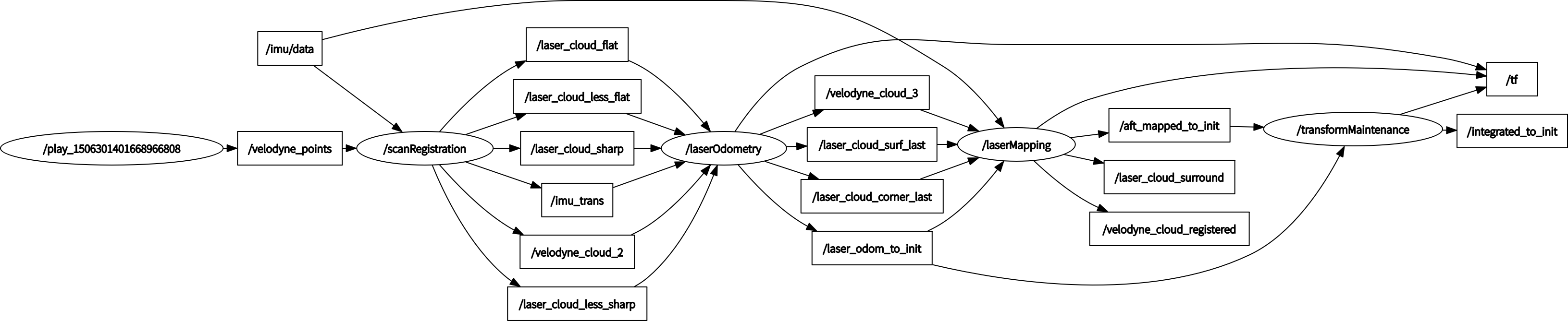
可以看到该节点订阅了laserOdometry节点发布的/laser_odom_to_init消息(Lidar里程计估计位姿到初始坐标系的变换)以及LaserMapping节点发布的/aft_mapped_to_init消息(laserMapping节点优化后的位姿到初始坐标系的变换),经过节点处理发布/integrated_to_init消息。
所以要搞清楚这个transformMaintenance节点到底是干嘛的,我们首先需要弄清楚它所发布的消息到底是什么含义。
这个节点的主函数非常简单:
int main(int argc, char** argv)
{
ros::init(argc, argv, "transformMaintenance");
ros::NodeHandle nh;
ros::Subscriber subLaserOdometry = nh.subscribe<nav_msgs::Odometry>
("/laser_odom_to_init", 5, laserOdometryHandler);
ros::Subscriber subOdomAftMapped = nh.subscribe<nav_msgs::Odometry>
("/aft_mapped_to_init", 5, odomAftMappedHandler);
ros::Publisher pubLaserOdometry2 = nh.advertise<nav_msgs::Odometry> ("/integrated_to_init", 5);
pubLaserOdometry2Pointer = &pubLaserOdometry2;
laserOdometry2.header.frame_id = "/camera_init";
laserOdometry2.child_frame_id = "/camera";
tf::TransformBroadcaster tfBroadcaster2;
tfBroadcaster2Pointer = &tfBroadcaster2;
laserOdometryTrans2.frame_id_ = "/camera_init";
laserOdometryTrans2.child_frame_id_ = "/camera";
ros::spin();
return 0;
}
可以看出/integrated_to_init消息是由发布器pubLaserOdometry2发布的,实际上就是由发布器pubLaserOdometry2Pointer发布的。我们顺藤摸瓜,找到pubLaserOdometry2Pointer的发布函数,发现每次接收到/laser_odom_to_init消息并调用回调函数laserOdometryHandler时,就发布一次该消息。
void laserOdometryHandler(const nav_msgs::Odometry::ConstPtr& laserOdometry)
{
double roll, pitch, yaw;
geometry_msgs::Quaternion geoQuat = laserOdometry->pose.pose.orientation;
tf::Matrix3x3(tf::Quaternion(geoQuat.z, -geoQuat.x, -geoQuat.y, geoQuat.w)).getRPY(roll, pitch, yaw);
transformSum[0] = -pitch;
transformSum[1] = -yaw;
transformSum[2] = roll;
transformSum[3] = laserOdometry->pose.pose.position.x;
transformSum[4] = laserOdometry->pose.pose.position.y;
transformSum[5] = laserOdometry->pose.pose.position.z;
// Lidar里程计估计位姿转到世界坐标系下
transformAssociateToMap();
// Lidar在世界坐标系下的姿态
geoQuat = tf::createQuaternionMsgFromRollPitchYaw
(transformMapped[2], -transformMapped[0], -transformMapped[1]);
// 发布Lidar在世界坐标系下的位姿
laserOdometry2.header.stamp = laserOdometry->header.stamp;
laserOdometry2.pose.pose.orientation.x = -geoQuat.y;
laserOdometry2.pose.pose.orientation.y = -geoQuat.z;
laserOdometry2.pose.pose.orientation.z = geoQuat.x;
laserOdometry2.pose.pose.orientation.w = geoQuat.w;
laserOdometry2.pose.pose.position.x = transformMapped[3];
laserOdometry2.pose.pose.position.y = transformMapped[4];
laserOdometry2.pose.pose.position.z = transformMapped[5];
pubLaserOdometry2Pointer->publish(laserOdometry2);
laserOdometryTrans2.stamp_ = laserOdometry->header.stamp;
laserOdometryTrans2.setRotation(tf::Quaternion(-geoQuat.y, -geoQuat.z, geoQuat.x, geoQuat.w));
laserOdometryTrans2.setOrigin(tf::Vector3(transformMapped[3], transformMapped[4], transformMapped[5]));
tfBroadcaster2Pointer->sendTransform(laserOdometryTrans2);
}
通过该回调函数可以看出,他完成的就是一个简单则坐标转换,得到经过laserMapping优化后的Lidar位姿。
但是!!!这里还是有个小坑的。正如我们刚才所说的,这个节点接收了两个消息,分别是laserOdometry节点和laserMapping节点发布的,而这两个节点发布的频率不同啊!!
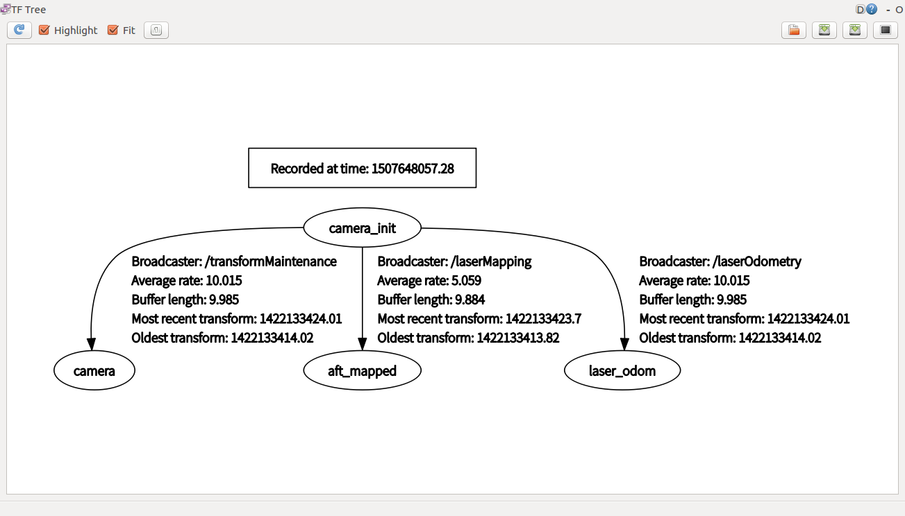
看图可以知道,论文中说1Hz和10Hz,实际是5Hz和10Hz。所以这个/integrated_to_init消息到底是什么?实际它就是融合后的Lidar轨迹,说白了就是:有优化结果了就拿这一时刻的优化结果作为轨迹,没有优化结果只有里程计结果了,就直接拿里程计结果作为这一时刻的轨迹。
3.运行和调试